Home » Without Label » 480 Volt Motor Wiring - Diagram 480 Volt 1 Phase Wiring Diagram Full Version Hd Quality Wiring Diagram Jdiagram Fimaanapoli It - 480 volt motor wiring diagram.
480 Volt Motor Wiring - Diagram 480 Volt 1 Phase Wiring Diagram Full Version Hd Quality Wiring Diagram Jdiagram Fimaanapoli It - 480 volt motor wiring diagram.
480 Volt Motor Wiring - Diagram 480 Volt 1 Phase Wiring Diagram Full Version Hd Quality Wiring Diagram Jdiagram Fimaanapoli It - 480 volt motor wiring diagram.. 2 speeds 1 direction 3 phase motor power and control diagrams. 5069f7e wiring diagram for 480 volt plug wiring resources. It is better to double check than to burn a motor up and release the magic smoke. 480v 3 phase motor wiring diagram. Control circuit until the start button is pressed once again.
Of course the coil voltage must be and the motor can be whatever voltage, this with a plc output straight to a starter and get rid of the start/stop switch. Legrand turnlok 20 amp 3 phase 480 volt black locking. 440 spark plug wiring diagram wiring diagram g11. On the motor there is a low voltage wiring and a high voltage wiring. Two speeds one direction three phase motor connection power and control diagrams.
Four Wire Delta Circuits Continental Control Systems Llc from r1spn12mh523ib7ly1ip4xkn-wpengine.netdna-ssl.com 440 spark plug wiring diagram wiring diagram g11. 480v 3 phase motor wiring diagram. Of course the coil voltage must be and the motor can be whatever voltage, this with a plc output straight to a starter and get rid of the start/stop switch. Disconnect all power from the system. The motor wire size calculator will calculate the proper wire size for a given motor hp and voltage. 5069f7e wiring diagram for 480 volt plug wiring resources. Effectively read a cabling diagram, one has to learn how typically the components in the system operate. There are 2 standard ways to correctly wire a 6 lead motor.
Legrand turnlok 20 amp 3 phase 480 volt black locking.
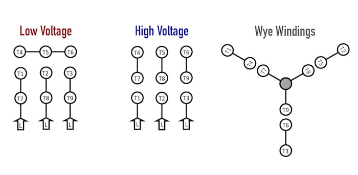
Call fox brothers motor repair in murfreesboro tennessee. Those nine leads provide an option for supplying power from either high or low voltage sources. 277 vac wiring diagram wiring schematic diagram. The coil is energized by the 120v, and the pushbuttons or other control devices operate at this same. 480 volt motor wiring diagram. 12 leads terminal wiring guide for dual voltage delta connected ac induction motor. Most use the high voltage wiring diagram only. Fuses open the circuit quickly in case of a massive overload or short circuit. Motors are usually protected by both fuses (or circuit breakers) and by heater coils in a magnetic starter. Just exercise just what we have enough money under as competently as evaluation wiring diagram for 12 lead 480. On both of these grounded 6 2010 dr motor common connection diagrams important notes 2 important notes. The motor wire size calculator will calculate the proper wire size for a given motor hp and voltage.
This video will show you how to wire up a 9 wire 3 phase motor to a 480 volt system.watch till the end for my tech tip.if performing on site, be sure to powe. 6 2010 dr motor common connection diagrams important notes 2 important notes. W2 cj2 ui vi wi High motor voltage, the motor is powered by an inverter, or electronic soft start. 277 vac wiring diagram wiring schematic diagram.
1 from Of course the coil voltage must be and the motor can be whatever voltage, this with a plc output straight to a starter and get rid of the start/stop switch. 12 leads terminal wiring guide for dual voltage delta connected ac induction motor. To add an additional remote station wire the new stop button in series with the. Those nine leads provide an option for supplying power from either high or low voltage sources. Otherwise, the arrangement will not work as it ought to be. Always use wiring diagram supplied on motor nameplate for motors with thermal protection single voltage / single rotation single voltage / reversible rotation. W2 cj2 ui vi wi This video will show you how to wire up a 9 wire 3 phase motor to a 480 volt system.watch till the end for my tech tip.if performing on site, be sure to powe.
3 phase motor winding resistance values, using ohm meter:
480 volt motor wiring diagram. 3 phase motor wiring diagram 12 leads. 480v motor wiring schematic baldor 12 lead motor wiring. The motor will supply the same amount of power, but with a different load amperage. On both of these grounded Strip back all motor leads with the wire strippers. On six lead single voltage motors watch out and check the manufacturer diagrams. Follow the book every time. L1 to t1, l2 to t2, l3 to t3, t4 to t7, t5 to t8 and t6. Some work, some do nothing, some destroy it. Always use wiring diagram supplied on motor nameplate for motors with thermal protection single voltage / single rotation single voltage / reversible rotation. 440 spark plug wiring diagram wiring diagram g11. Of course the coil voltage must be and the motor can be whatever voltage, this with a plc output straight to a starter and get rid of the start/stop switch.
277 vac wiring diagram wiring schematic diagram. 6 2010 dr motor common connection diagrams important notes 2 important notes. Each part ought to be placed and connected with other parts in particular way. The motor wire size calculator will calculate the proper wire size for a given motor hp and voltage. Legrand turnlok 20 amp 3 phase 480 volt black locking.
Common Motor Windings And Wiring For Three Phase Motors Technical Articles from control.com Phase heater wiring diagram on 480v 3 phase heater wiring diagram. 480 volt 3 phase 6 lead wiring diagram disclaimer. 12 lead 480 volt motor wiring. Control circuit until the start button is pressed once again. O/l = over load relay. The supply voltage is either 240 volts alternating current (vac) or 480 vac. Each part ought to be placed and connected with other parts in particular way. 6 2010 dr motor common connection diagrams important notes 2 important notes.
440 spark plug wiring diagram wiring diagram g11.
Not all motor manufacturers use the same type of windings. 2 speeds 1 direction 3 phase motor power and control diagrams. Check all three wires singly t1, t2, t3 (three phases) to the ground wire. O/l = over load relay. W2 cj2 ui vi wi Otherwise, the arrangement will not work as it ought to be. Follow the book every time. On six lead single voltage motors watch out and check the manufacturer diagrams. Electrical motors 12 lead, dual voltage, wye start/delta run, both voltages or 6 lead, single voltage, wye start/delta run motors designed by us motors for wye start, delta run may also be used for across the line starting using only the delta connection. If it's zero or reads some continuity at all, then a problem is present with the motor or cable. 277 vac wiring diagram wiring schematic diagram. High motor voltage, the motor is powered by an inverter, or electronic soft start. 277/480 volt wire color standards.